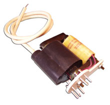
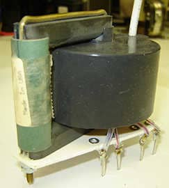
The flyback transformer is a special type of transformer, which produces high voltage, high-frequency electric signals, that are basically saw-tooth signals. It is also called as the line output transformer (LOPT). It is exclusively used in modern electronic applications like CRT displays, LED fixtures, solar micro-inverters, telecom, AC-DC power supply, and many more. Since this device is of great use in modern electronics, it is essential to be literate about its design/construction, function, and range of applications. Are you aware of all these factors? If you are not, then this post holds all the answers. This post introduces you to flyback transformer design and construction, its working principle, and its significant industrial applications.

An Overview of Flyback Transformer
The flyback transformer is an inductor featuring conductive coils called primary and secondary winding with an inductive gap in between. As the input voltage is applied to the primary winding, it generates electric energy which is first stored between the gap and then is transferred to the secondary winding. It works on the basis of flyback topology in which the energy generated is first stored in the form of a magnetic switch and then is transferred to secondary winding after switching the cycle. These flyback transformers are used as voltage converters or circuit isolators. Generally, the flyback transformer is designed to be an integrated part of flyback converters and then is installed for several applications.
Flyback Transformer Design/Construction
The flyback transformer is a special type of transformer, poses a slightly different design or construction layout. In order to give a better understanding of the flyback transformer, the flyback transformer design layout is discussed below.
- At first, the primary coil is wound on a winding form or bobbin. It generates the first portion of the inductor circuit.
- Further, the secondary coil is wound around the primary winding. This generates the secondary portion of the inductor circuit. This construction of secondary winding around the primary one is specially designed to minimize leakage inductance. The secondary winding is further layered a film insulation to offer more dielectric material for high voltage parts of the assembly.
- Finally, a gapped ferrite core is assembled with the primary/secondary winding arrangement. This gap increases the magnetic reluctance. The magnetic field lines remain enclosed within the core gap and winding.
However, this construction or design layout is traditional. It is further integrated with a primary switch, input capacitor, output capacitor, and output rectifiers in real-time industrial applications. The primary switch enables the flow of voltage through the primary winding, the input/output capacitors are attached to flyback transformer assembly in order to store electric current. The output rectifier is reverse biased and prevents secondary current flow while the primary is energizing the core gap.

Working Principle of Flyback Transformer
As mentioned earlier, a flyback transformer functions on basis of flyback topology. However, in real-time operation, the flyback transformer is installed in an integrated circuit with other electronic devices, where its function differs slightly by the topology/protocol remains the same. The real-time working of a flyback transformer is detailed as follows.
- In an integrated circuit, a flyback transformer is powered by turning on a primary switch. As the switch is turned on, DC voltage is passed through the primary winding.
- As the current passes through the primary winding, primary inductance is generated in the ramp.
- The generated inductance is stored in the form of magnetic field/energy in the inductive gap of the transformer. This energy storage takes place in accordance with flyback topology. The energy is stored in the gap until it receives a command from the secondary winding.
- The secondary winding is integrated with an integral diode that transmits the current to an electronic device in the series. Therefore, once the diode commands for current, the energy stored in the gap is transferred to the secondary winding.
- From the secondary winding, the current is then transferred to the diode in series and then to the electronic device.
This completes one cycle of a flyback transformer. However, the cycle can be repeated if the secondary coil discharges the current to zero. This means if there is no stored current remaining in the gap then the secondary coil discharges at zero or discontinuous condition. If the amount of current remains stored in the gap, then it is called continuous transformer mode.
Now that the flyback transformer is introduced along with its design layout and working principle, it is important to acknowledge that the quality of the flyback transformer impact on its performance. Therefore, if you aim to source quality flyback transformer, then you must buy it from trusted manufacturers like Custom Coils. The company has been a prominent supplier of various transformers and inductors since 1967.
